There’s a lot of variation in how different people approach pressure gauges. After all, competition within the industry is a very real thing. Everyone’s trying to figure out their own unique style which might give them a competitive advantage. But there are a few things which everyone can agree on. And one of the most important is that the quality of work often depends on the quality of parts used within the larger system as a whole.
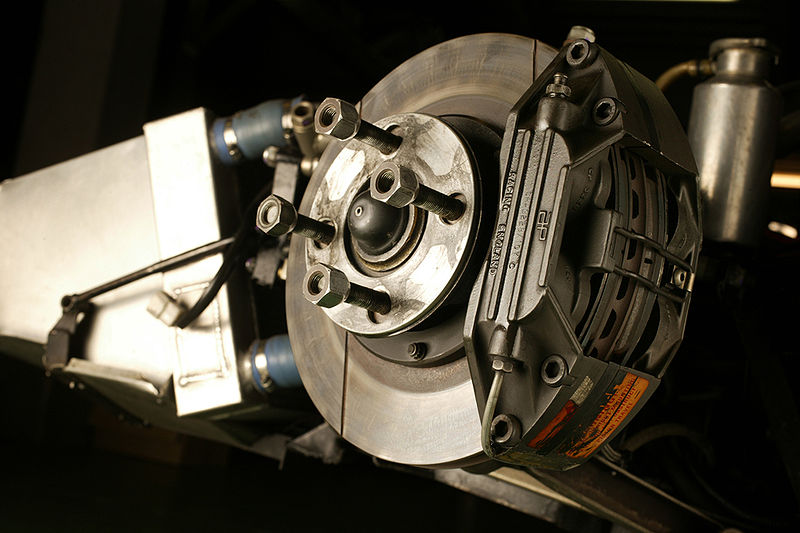
Take industrial clutches and brakes for example. Imagine just how strong and versatile a brake needs to be if it’ll provide proper stopping force within gantries, cranes, landry equipment, steel mills and a wide variety of other applications. Anything which needs rapid movement will require rapid cessation of that movement as well. And the various clutches and brakes have a lot of demanding force put upon them. There are a few points one can consider which should ensure that any clutch or brake is right for the job.
The first thing to consider is that there is a distinct difference between industrial clutches and brakes. Not just in models, but between clutches and brakes themselves. Clutches are used to transfer torque. Brakes are usually used to stop a rotating load. But they can be used as a means of stopping almost any load. One should choose brakes for situations where accurate stopping of the load is a necessity. Additionally the motor should stop as a part of this process. A clutch is instead used in situations where the load and motor are engaged or disengaged while the motor runs. And a combination of the two can also be used when a load is started or stopped while the motor continues to rotate.
Net, one should try to define the rpm where the device will be mounted. If a motor has been sized appropriately to the application then one can use a quick-selection chart which categorizes by unit sizes. However, in some circumstances one might need to talk to the application support staff or the manufacturers in relation to this issue.
The next step in this process involves the motor frame size. The motor frame size impacts shaft size. And there’s seldom any real variation in the ratio here. As such one can usually just confer with manufacturer provided charts to determine motor frame size and shaft size.
The next stage involves consideration of unit mounting. Both of these devices can be base mounted or mount to the motor shaft. And of course the belt drive, chain drive or the coupling will also intersect with the device as input. Thankfully this is a fairly easy step if the prior investigatory steps have been taken into account.
One also needs to keep a few numbers in mind. Many people will recognize the triad of 6,24 and 90. These are the most common coil voltages one will need to work with. 90 volt is most common in the US. Meanwhile Europe tends to use 24 volt. It’s important to keep in mind that manufacturers can tackle the long standing issue of AC/DC voltage if needed too. This is usually more a matter of planning than it is of full incompatibility.
If all of this is kept in mind then it should be fairly easy to ensure that the choice of clutch and brake goes smoothly. The vast majority of the work simply comes down to researching the specs of one’s machinery. Once that data has been tracked down and verified the actual comparison shopping is usually fairly easy. And more a matter of building up manufacturer experience and loyalty than anything.

